Finding your Keyboard's Pinout
Understanding the pinout of your keyboard's cable is a neccessary step when wiring up a converter. However, randomly attempting to identify pins through trial-and-error poses the risk of potential damage. This concern is especially prevalent when dealing with the VCC (+5V) pin, as inadvertently shorting it to another pin (i.e. GND) can result in permanent damage. Adhering to the following methods below allow for a safe determination of the keyboard's pinout.
Note: A multimeter will be required for the following methods.
Prerequisite: Multimeter
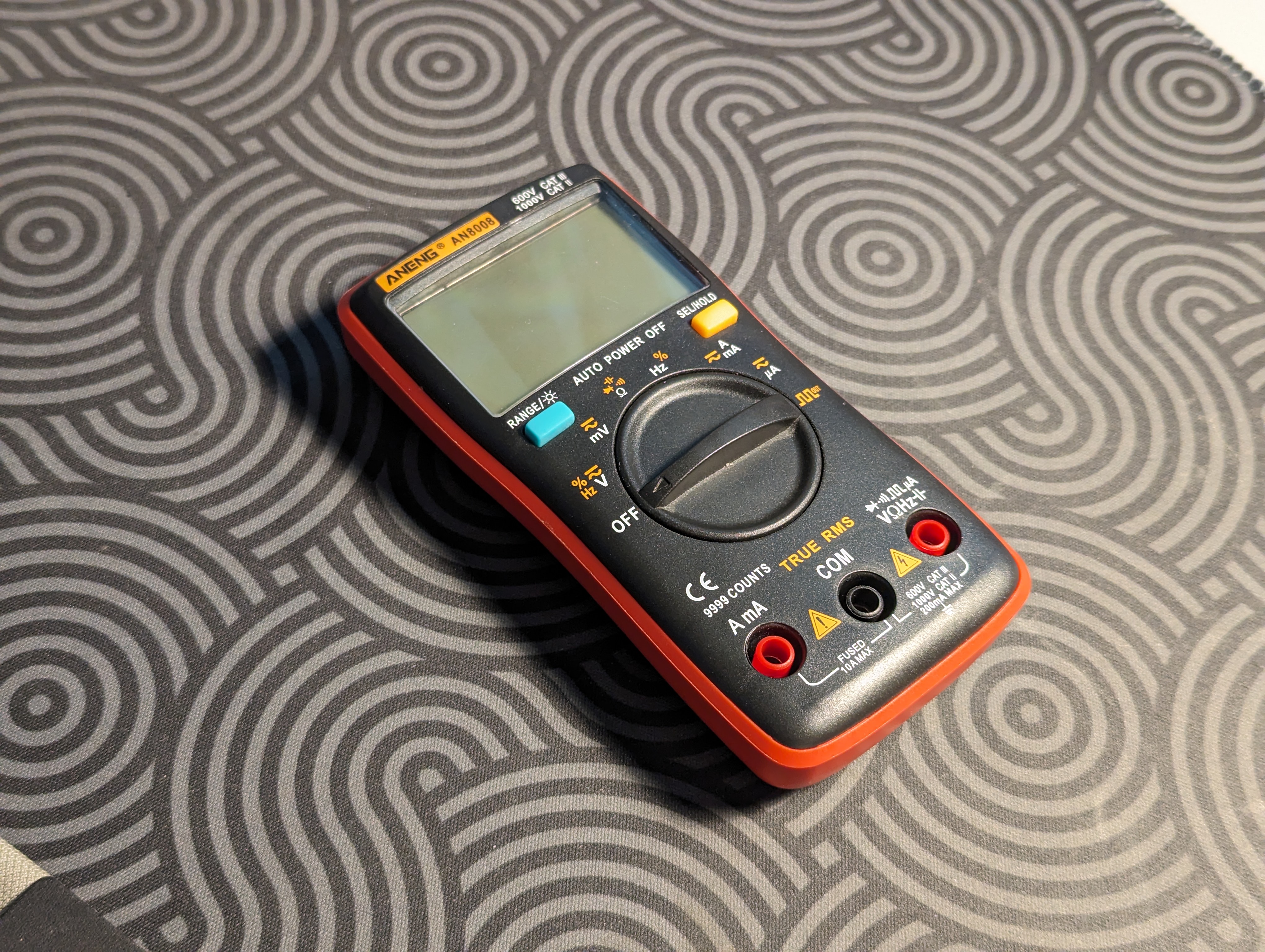
This segment will guide you through preparing your multimeter, complete with an illustrative example of its operation.
Switch to Resistance mode
For all the following methods, the dial on your multimeter must be set to the “Resistance mode”, which typically represented by the Ω symbol.
This mode depicts how easy it is for electricity to travel through a medium, such as a wire.

Demonstration
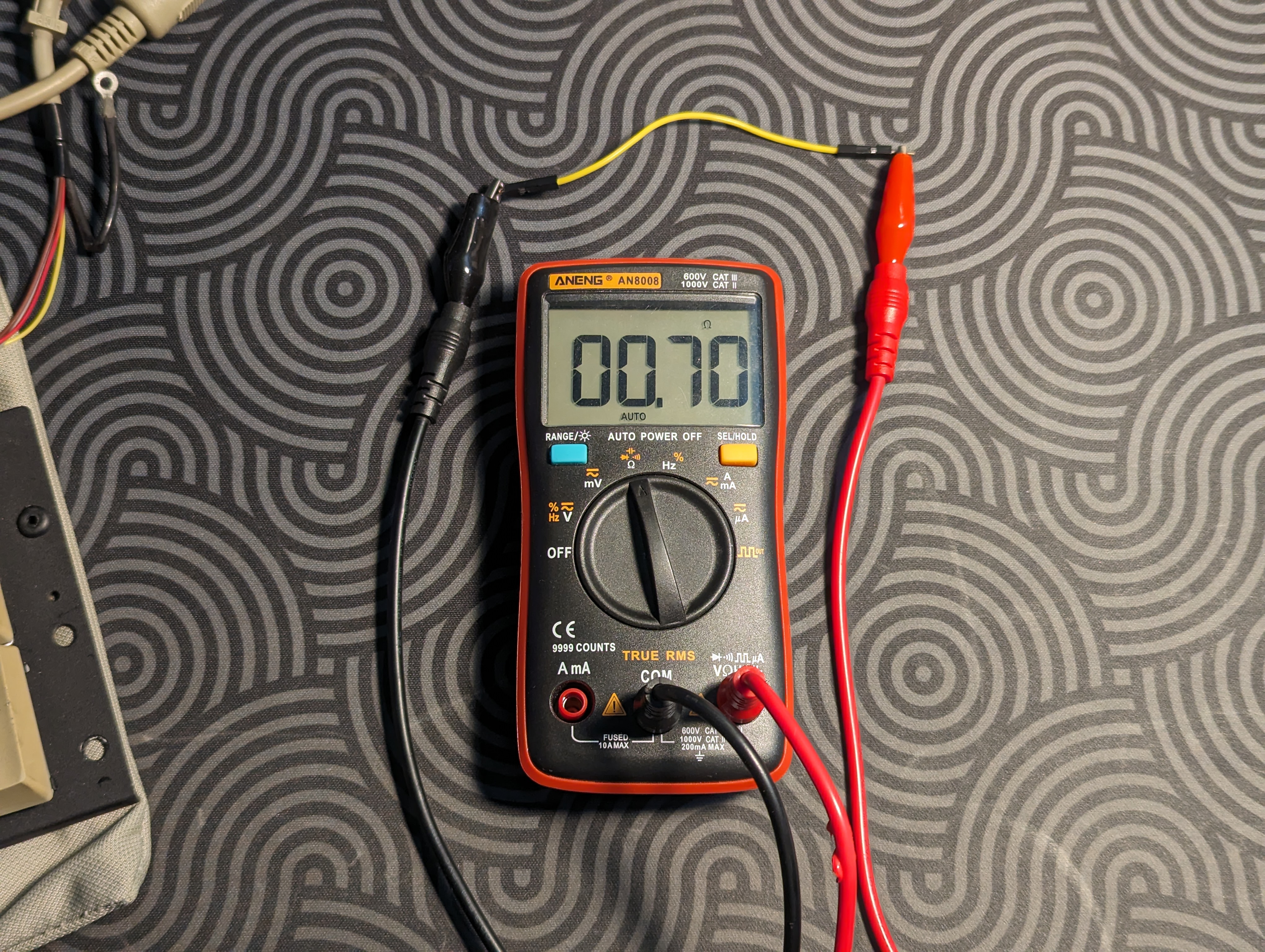
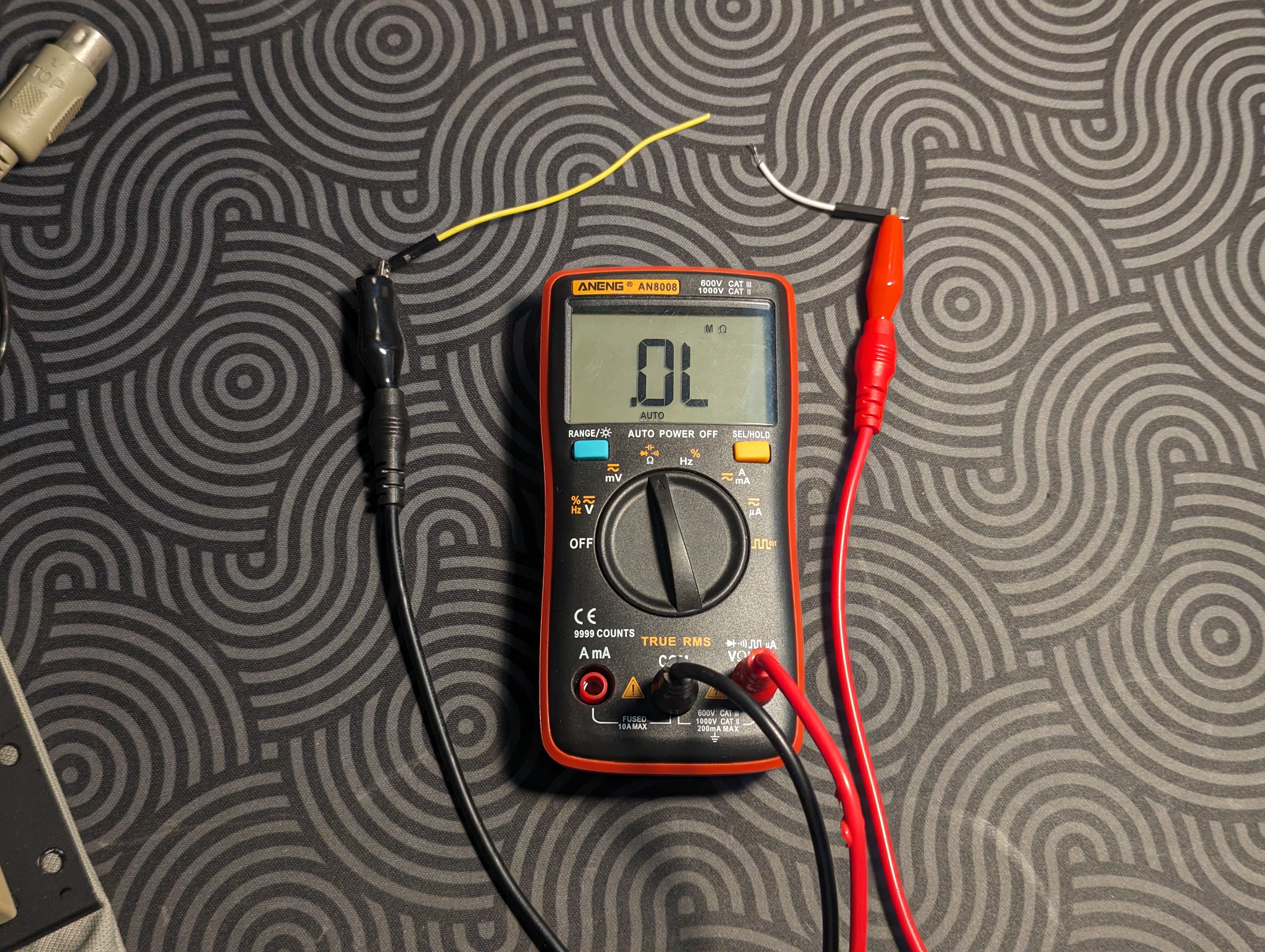
When in Resistance mode, the multimeter can show you when two ends are connected. The photos below demonstrate the following:
- In the first photo above, the multimeter demonstrates that both ends of the yellow wire are connected, as signified by the 0.7Ω reading.
- However, once the yellow wire is broken up, the multimeter reads “.OL”, signifying that no connection can be found between the two ends.
- Using this information, we can trace the path of any pin in a keyboard.
Note: For a healthy connection, the multimeter must read a small and stable number. Larger numbers represent more resistance.
Method 1: Using the Original Cable

Note: An NTC KB-6153 will be used for demonstration purposes.
1) Lookup the connector's pinout
Cable connectors follow a standardized pinout in most cases, and are already documented online.
 Example: In this demonstration, the NTC KB-6153 uses an XT/AT connector.
Caution: In this demonstration, the diagram had to be flipped horizontally to match the male version.
2) Search for connections
2.1) Probe the PCB's Pin
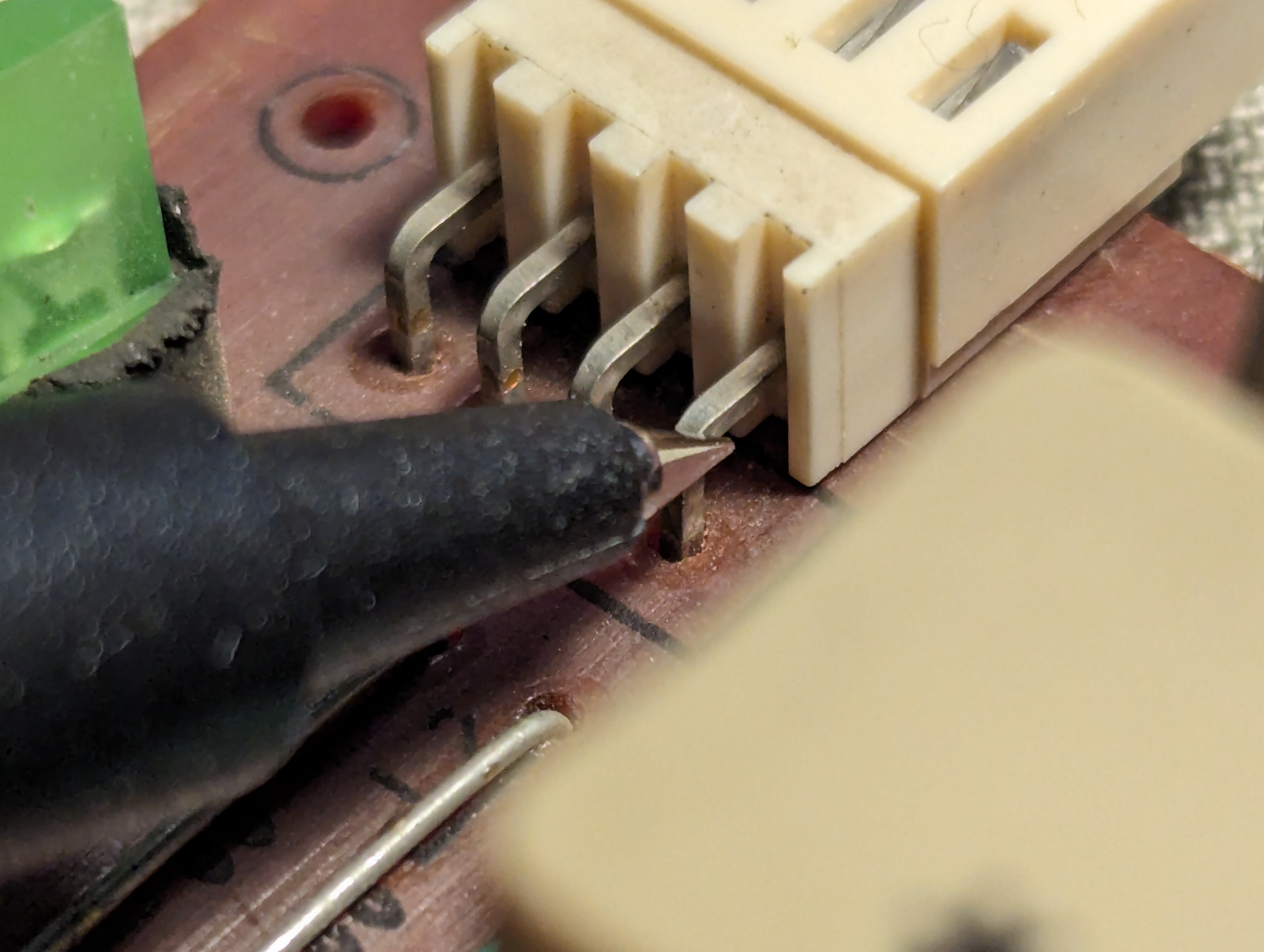
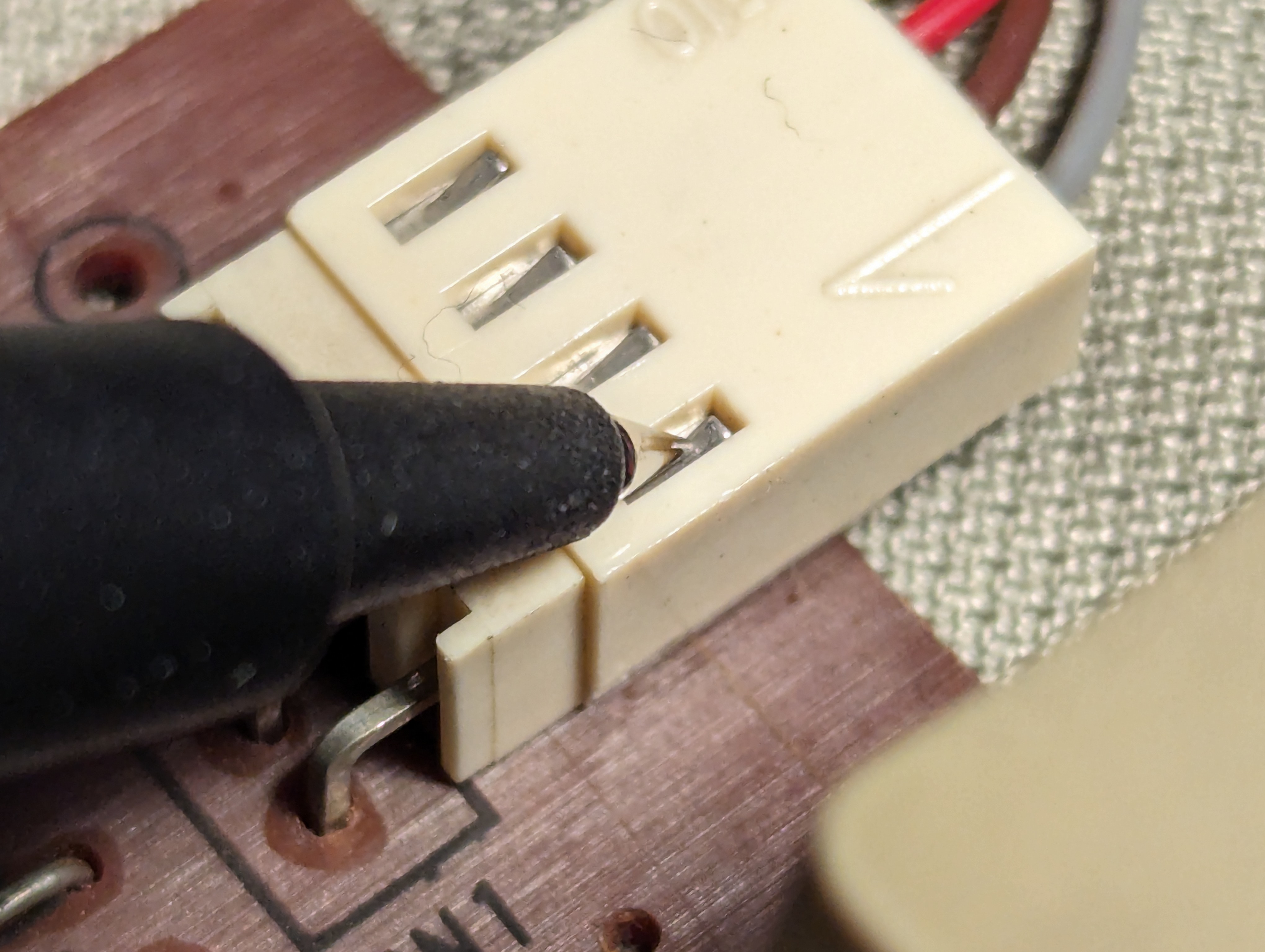
Connect one probe to a pin on the PCB. Any pin can be chosen here, but for this demonstration, the 4th pin is chosen.
Note: As shown above, a pin can probed from multiple areas.
2.2) Find the connected pin
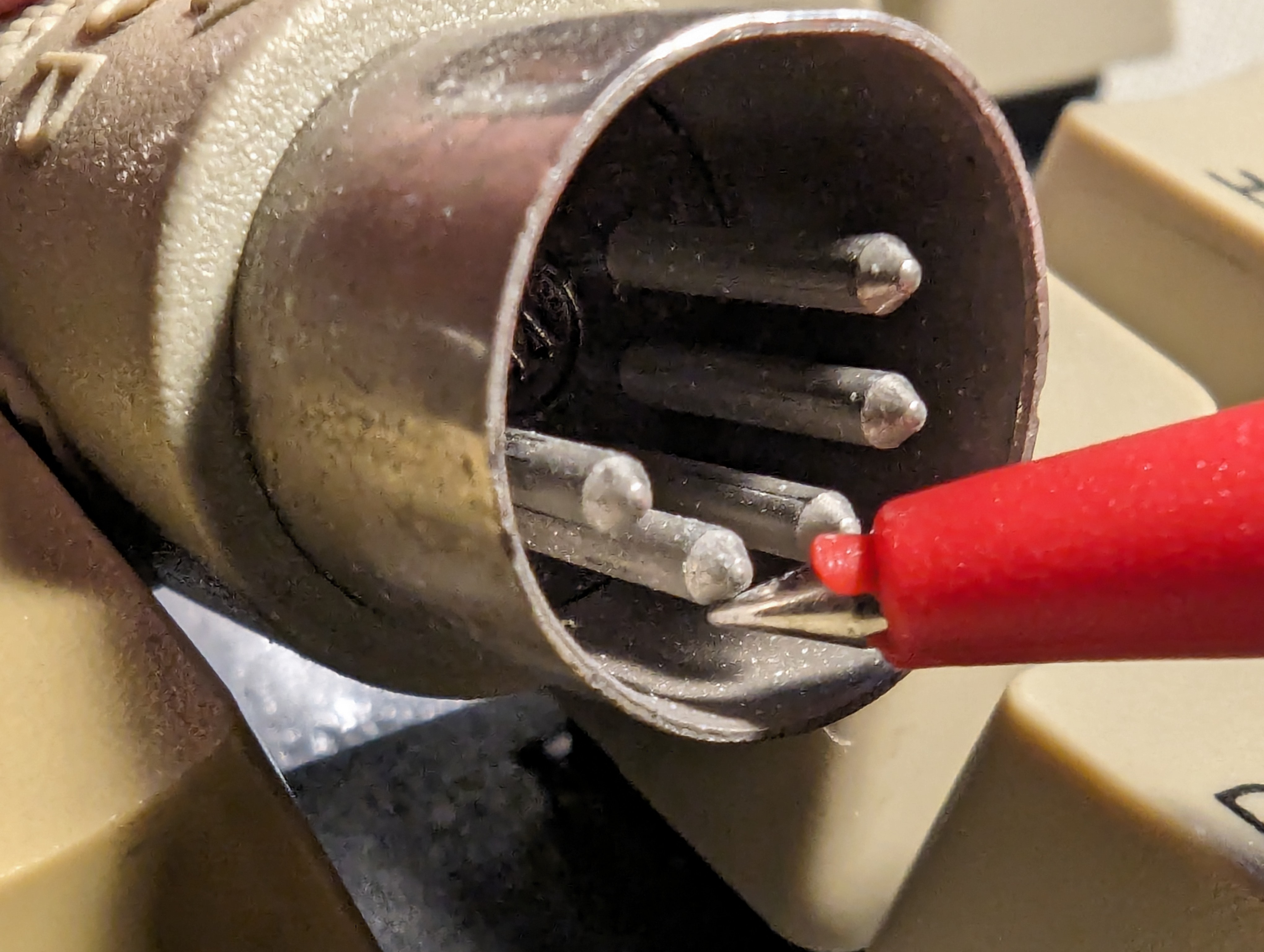
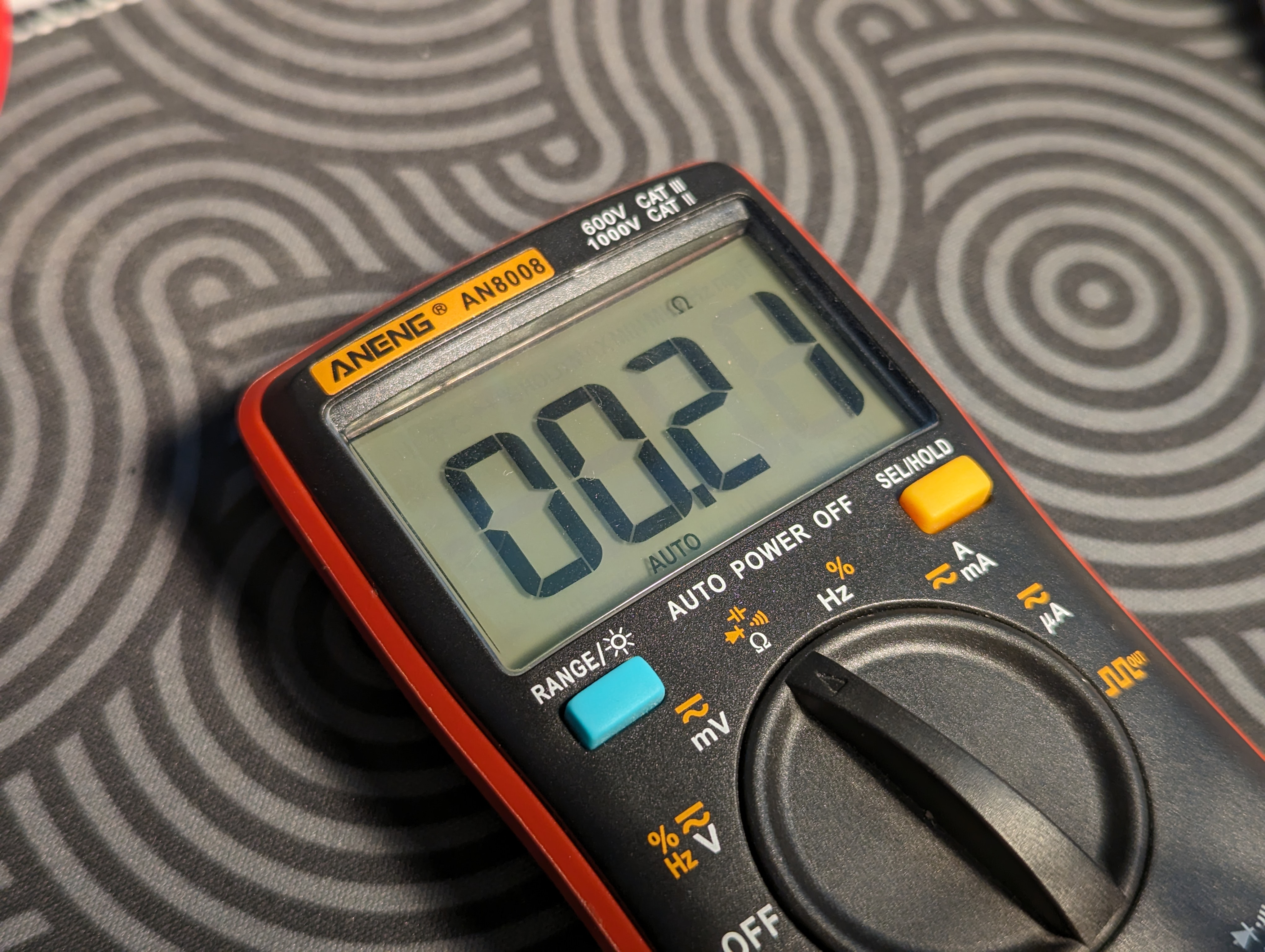
Using the other probe of your multimeter, find the pin on the connector that's connected to the PCB pin.
Note: Cycle through all the pins until you find a pin where the multimeter reads a small and stable number.
2.3) Note it down!
When a stable connection is detected, refer back to connector's diagram to confirm the pin's name.
 Example: In this demonstration, the 4th pin is connected to GND on the diagram.
Method 2: Using the Keyboard's Main Chip
[WIP]

