This is an old revision of the document!
BTC 5100 series
This page is currently a work in progress, with only the foam and foil BTC 5100 properly documented. If you have any documentation or images of the BTC 5100 or BTC 5100C; please feel free to provide and document them!
| BTC 5100 | |
 |
|
| Switch | BTC tactile foam and foil |
| Sense method | Capacitive |
| Protocol | AT, PS/2 |
| Keycaps | Laser-engraved ABS |
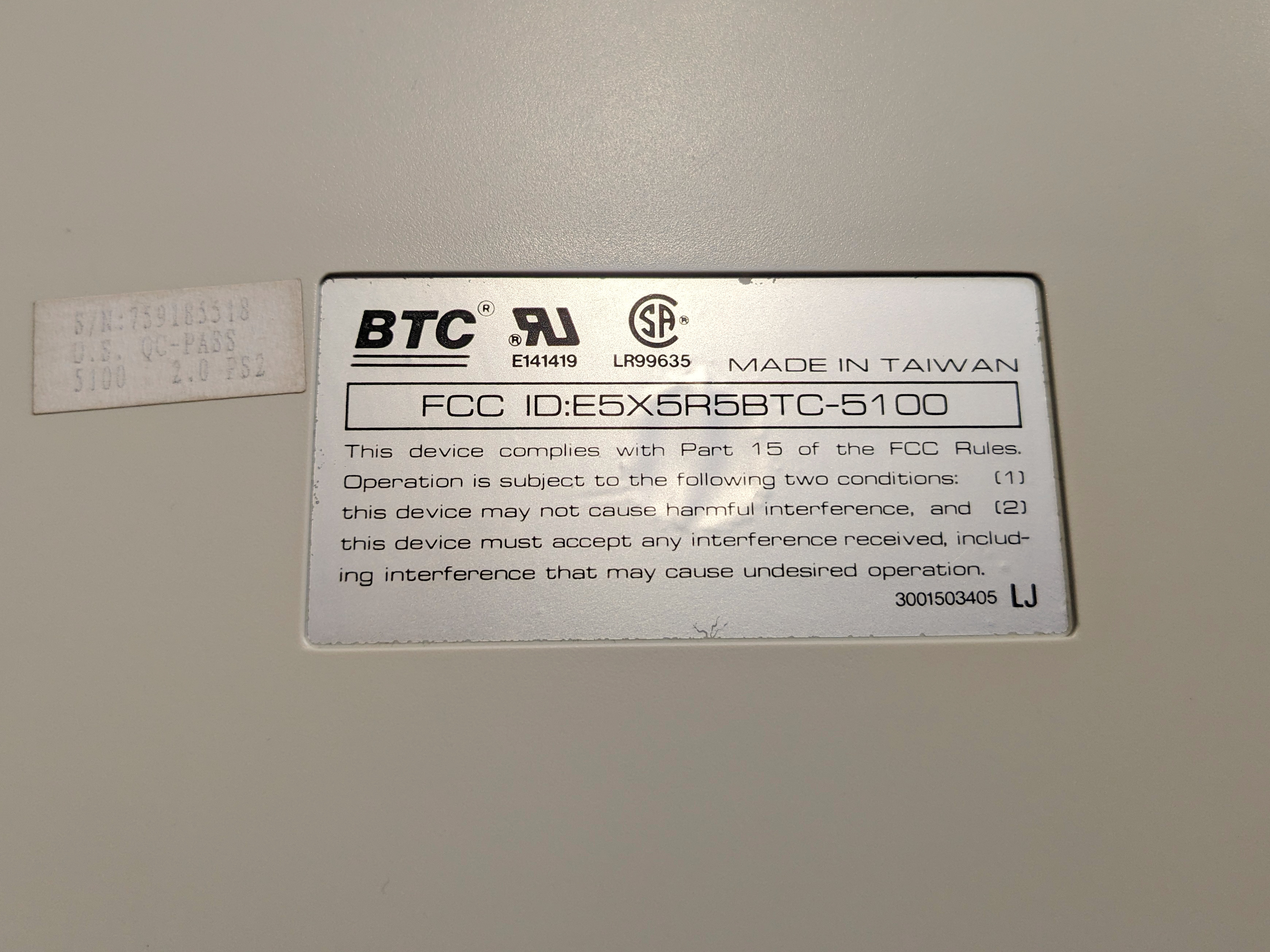
| FCC ID | E5X5R5BTC-5100 |
BTC 5100 is used to describe two similar-looking compact keyboards produced by BTC: the BTC 5100 using their capacitive tactile foam and foil switches, and the BTC 5100C that utilizes thier conductive dome with slider system over a PCB.
Description
Everything below this point is currently used to describe the BTC 5100 foam and foil keyboard. Please do not rely on this information here as a teardown of the BTC 5100C dome with slider keyboard.
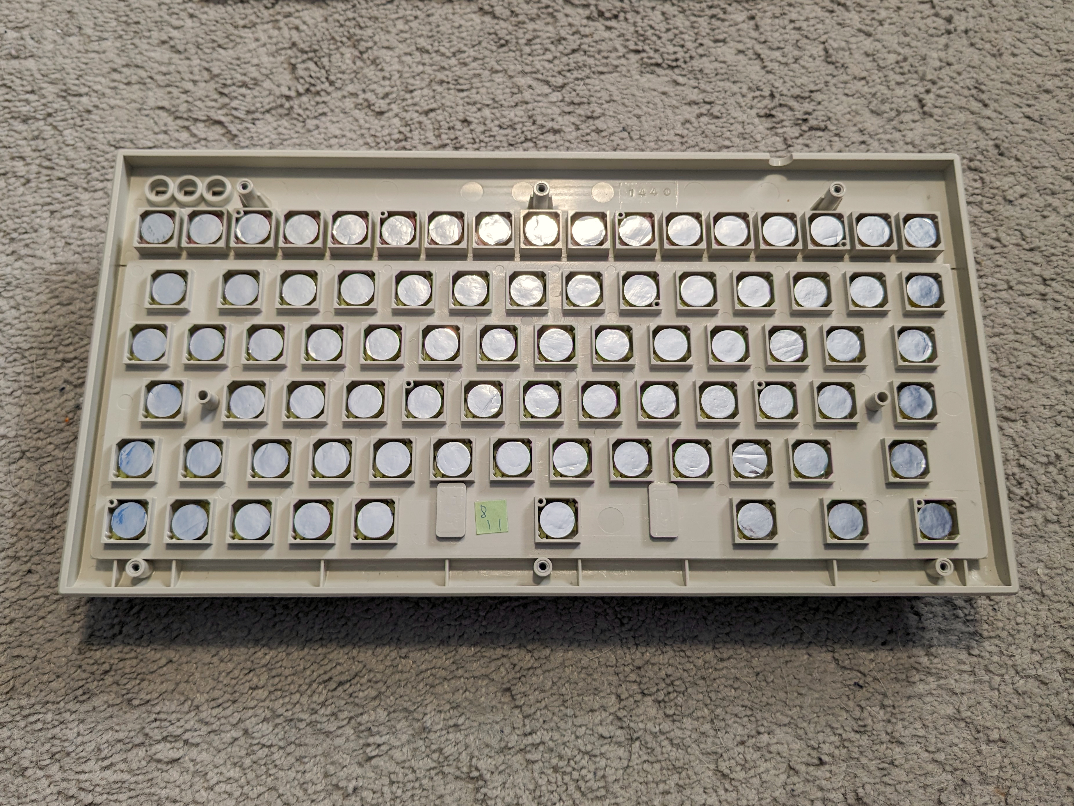
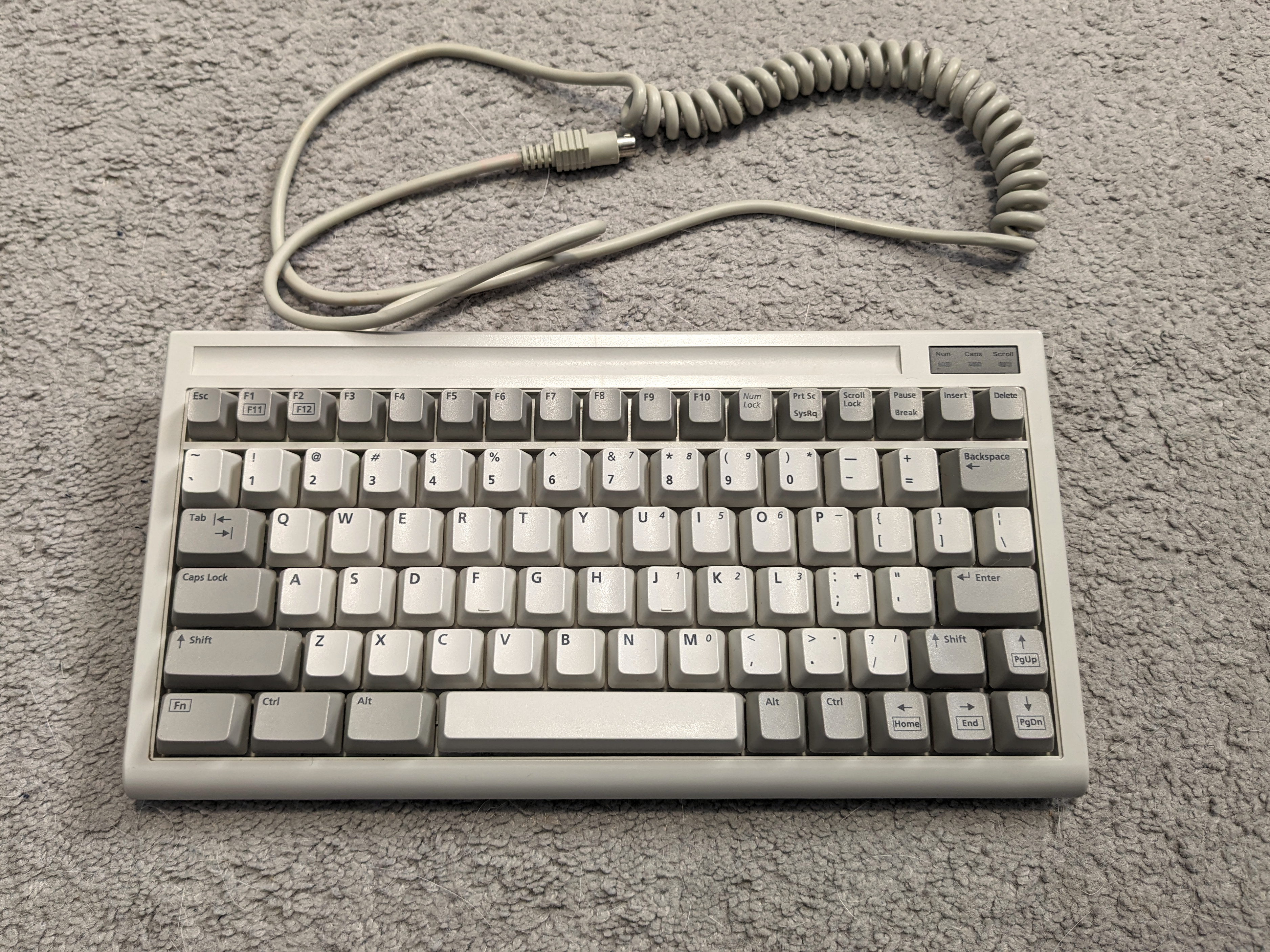
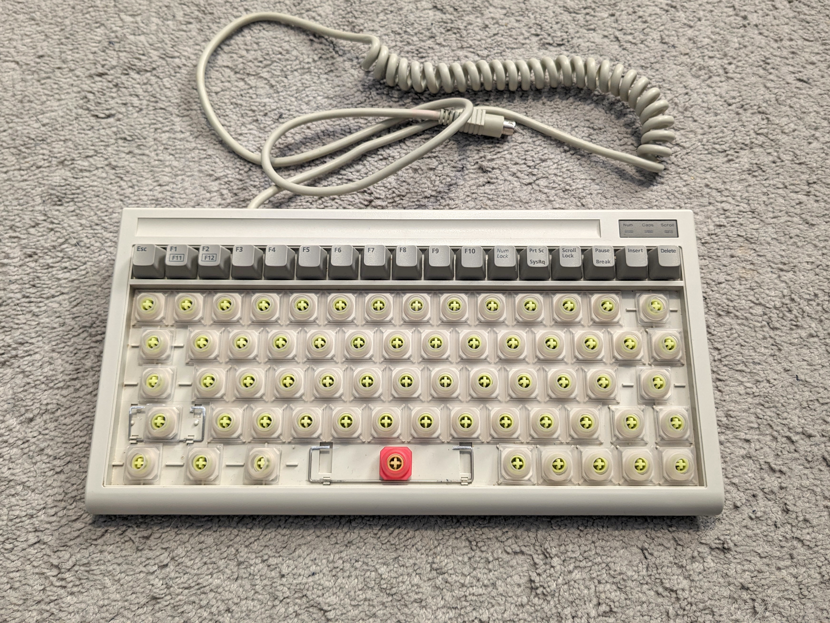
This keyboard crams all of the keys from a full-size keyboard into a 80 key compact keyboard through several design decisions. The alphanumeric block utilizes a 60%-style layout that truncates the right Alt and Ctrl keys along with splitting the right Shift key to make space for an L-shaped arrow key cluster in the bottom-right corner. Furthermore, the keyboard shortens the right side of the keyboard, visible with the Backspace, “pipe/backslash”, and Enter keys; causing the keyboard to be 14.5 units wide. This main alphanumeric block utilizes BTC tactile foam and foil switches, with a Cherry MX compatible keycap mount.
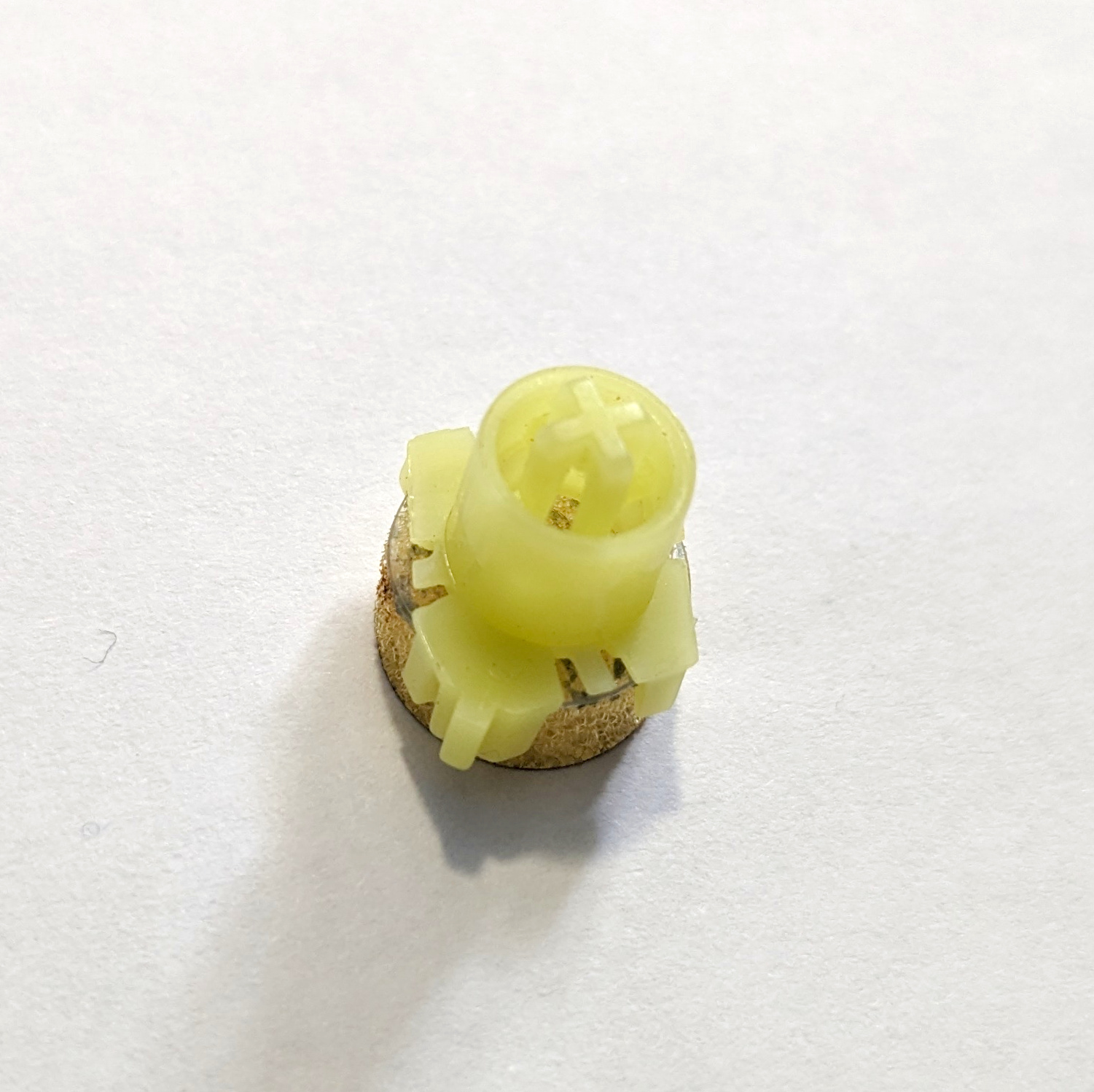
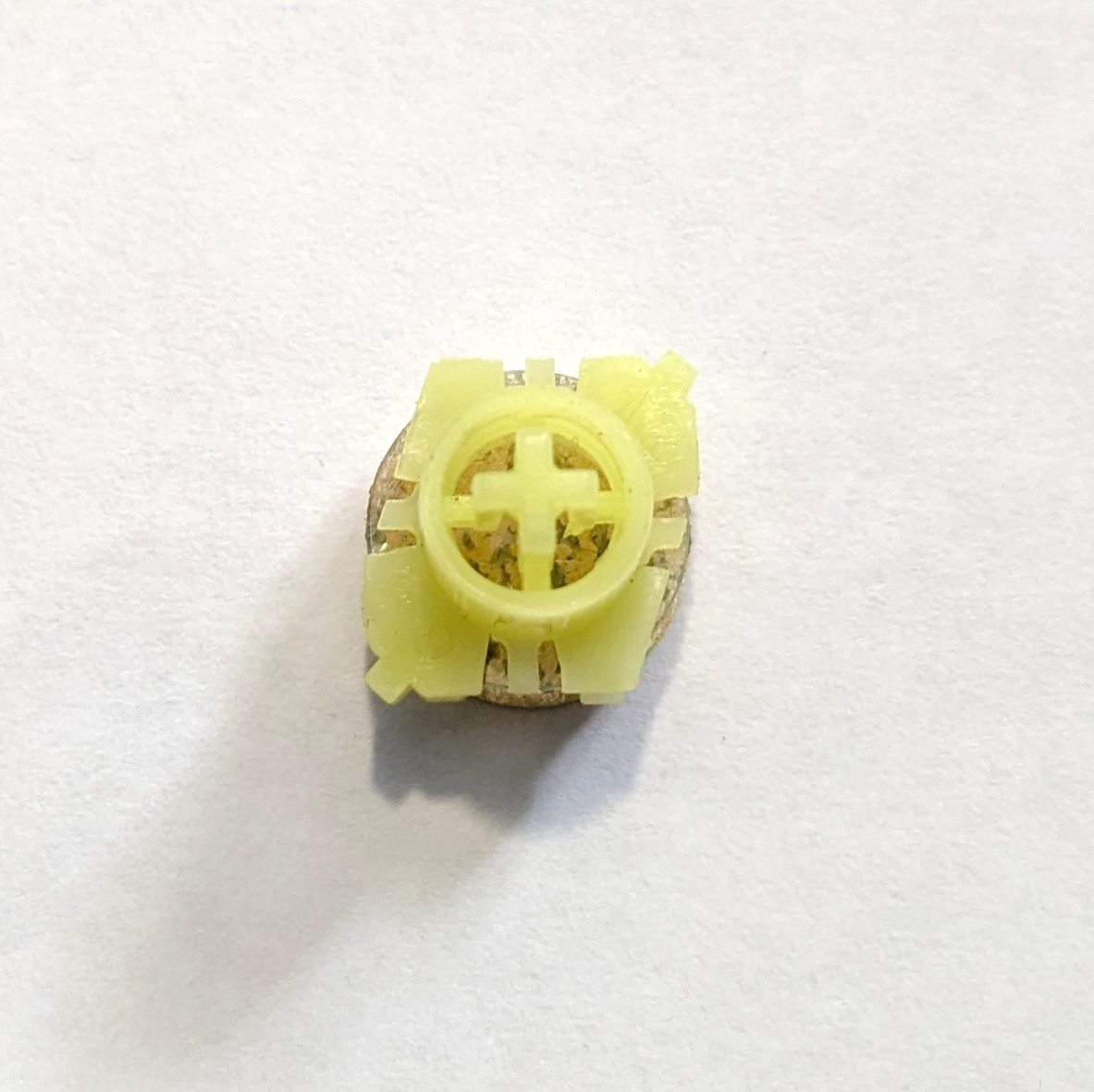
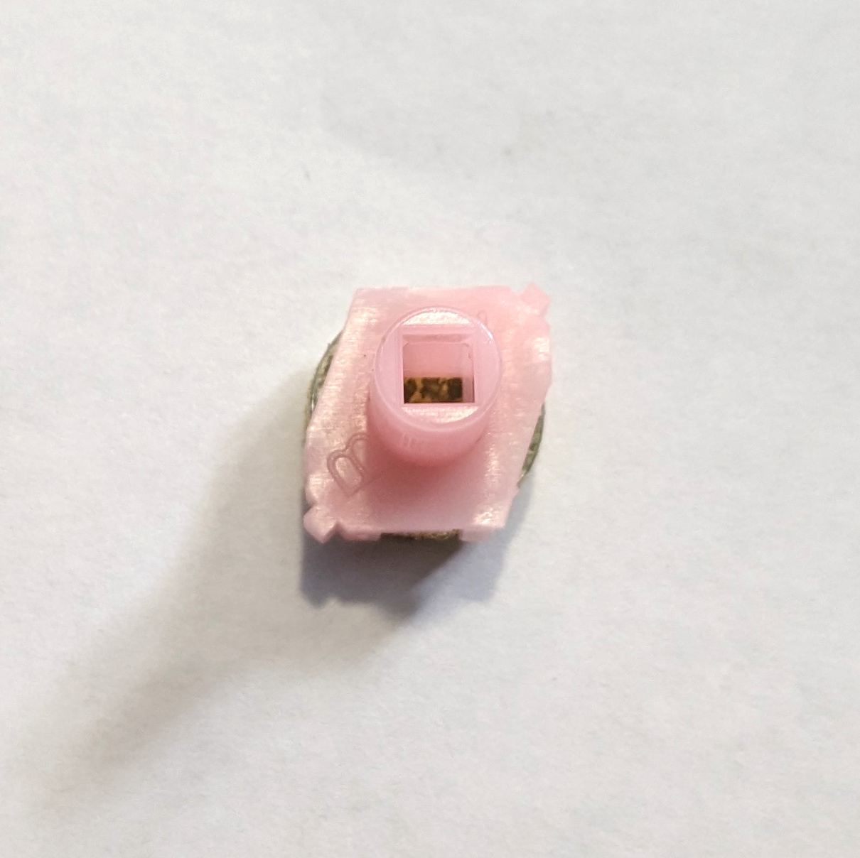
The keyboard keeps the function row from a standard full-size layout, but heavily modifies the layout. The top row omits any spacers, only features 10 physical “function” keys, and crams in three additional keys into the top row - “Num Lock”, Insert, and Delete keys. Furthermore, this top row features keys that are slightly smaller than normal keys, cramming 17 keys into the same 14.5 unit width. This top row utilizes a “compact” variant of BTC linear foam and foil switches, with a square keycap mount. The square hole used here is slightly smaller than the one used on Mitsumi keyboards with a similar square mount.
The keyboard utilizes a “function key” to provide access to other various keys, as indicated via sublegends. This includes accessing F11 and F12 via F1 and F2, along with accessing navigation keys via the arrow keys.
Finally, the board features an integrated number pad with its location indicated by sublegends, aligning with the 7, 8, and 9 keys in the number row. It can be toggled on or off by using the “Num Lock” key. Furthermore, you can temporarily access the other layer by momentarily holding down the “Fn” key whilst pressing the associated key - for instance, temporarily accessing the number pad whilst “Num Lock” is off, or accessing the standard alphanumerical block whilst “Num Lock” is on.
The keyboard came with either a 5-pin DIN plug for AT variants, or 6-pin Mini-DIN plug for PS/2 versions. Furthermore, the keyboard is known to come in either pebble and ivory or black 1) coloured variants.
Construction
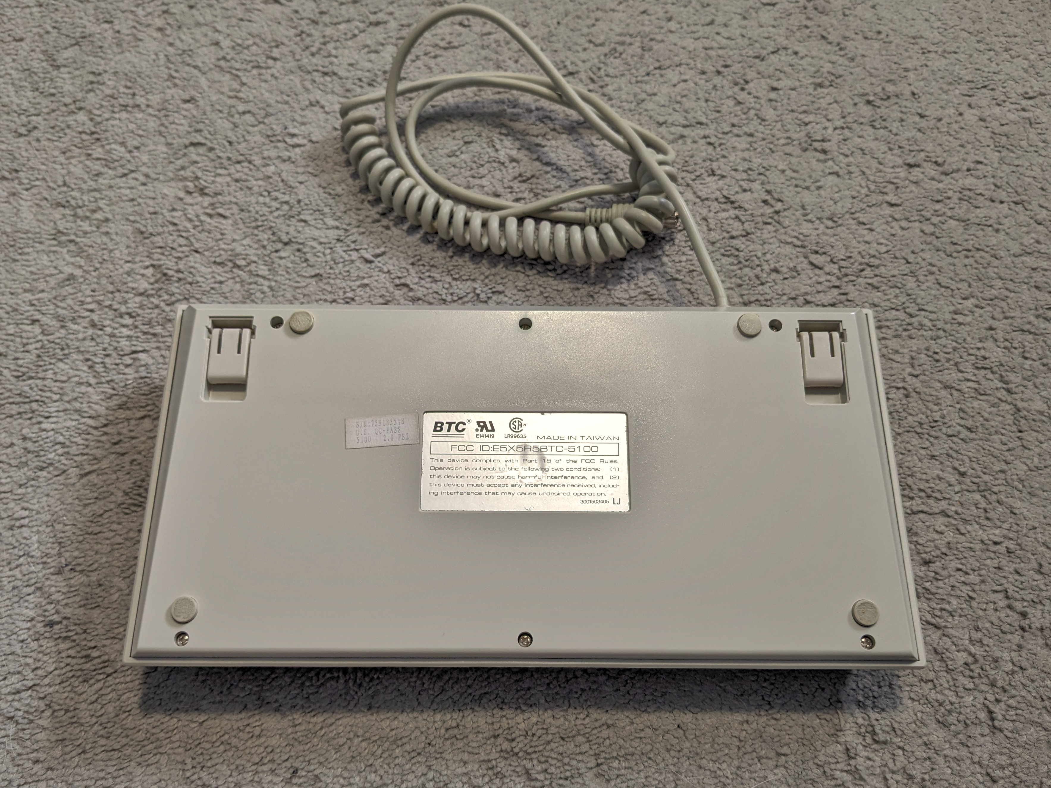
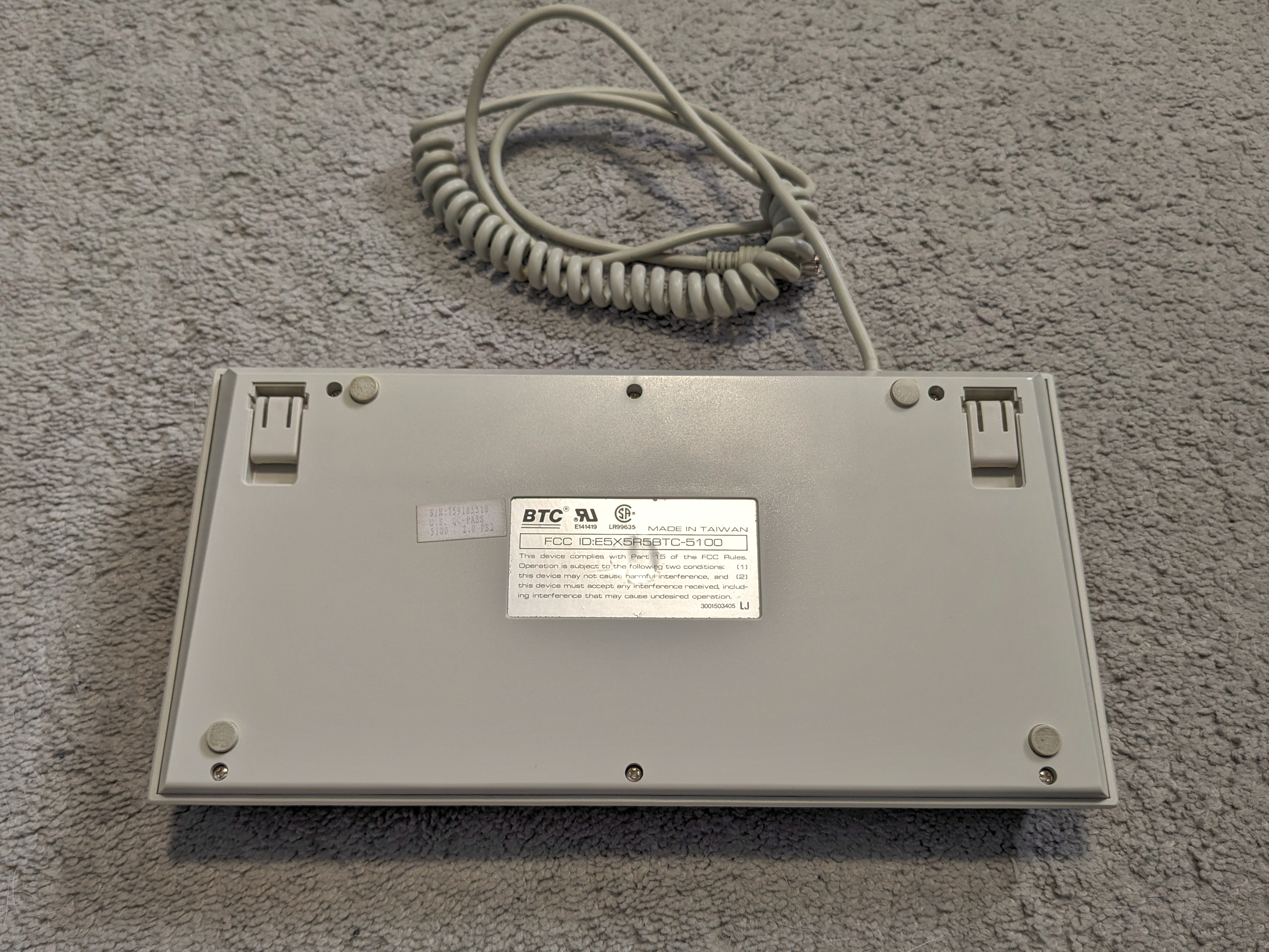
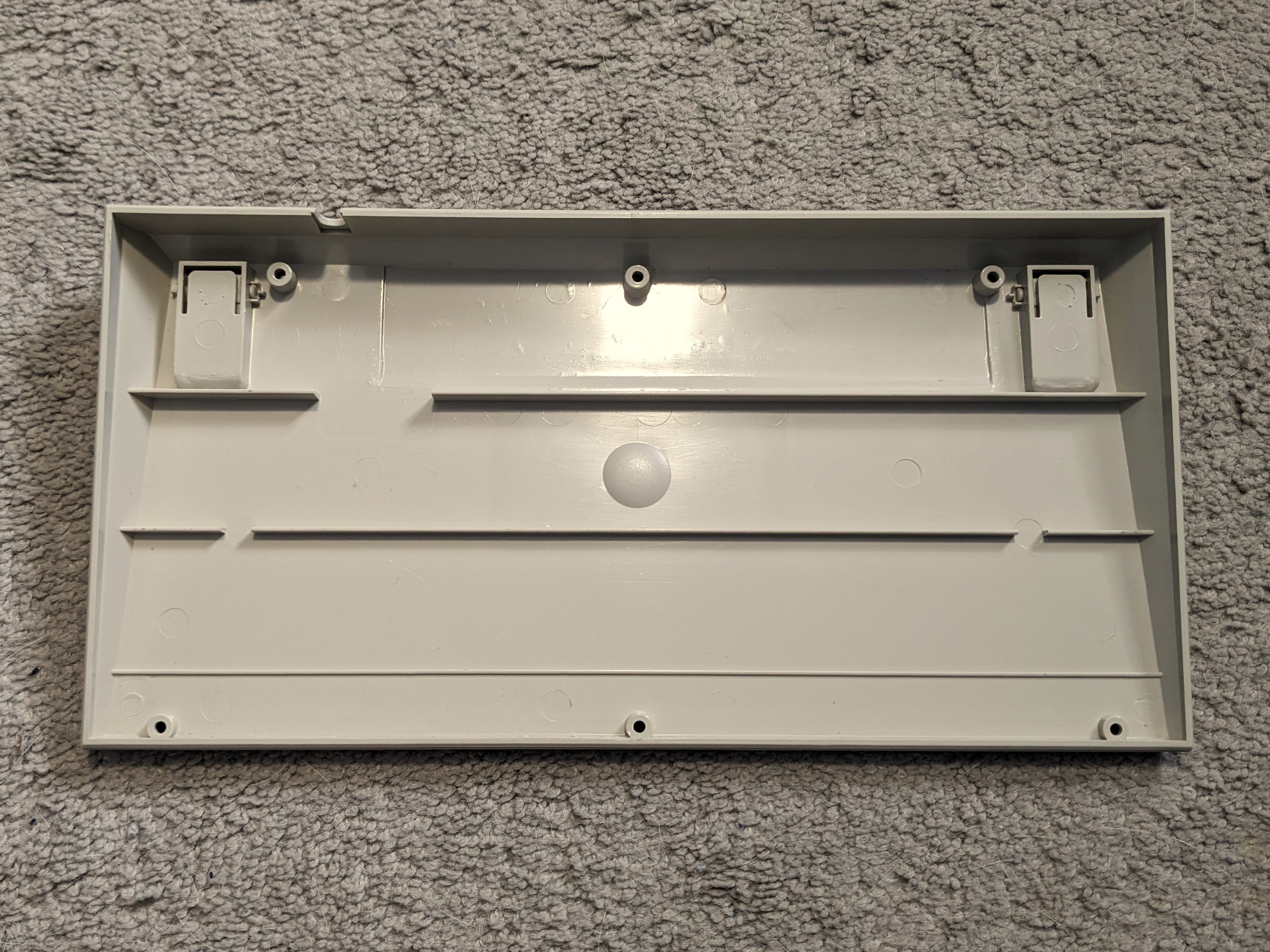
The keyboard features a top case with an integrated plate. The top case screws into the bottom case via six screws at the bottom. The bottom case has four anti-slip rubber pads on the case, along with two flip-out feet to adjust the typing angle. The flip out feet do not have rubber padding. The bottom case features two stickers - one listing the serial number and variant, and the other listing the FCC ID.
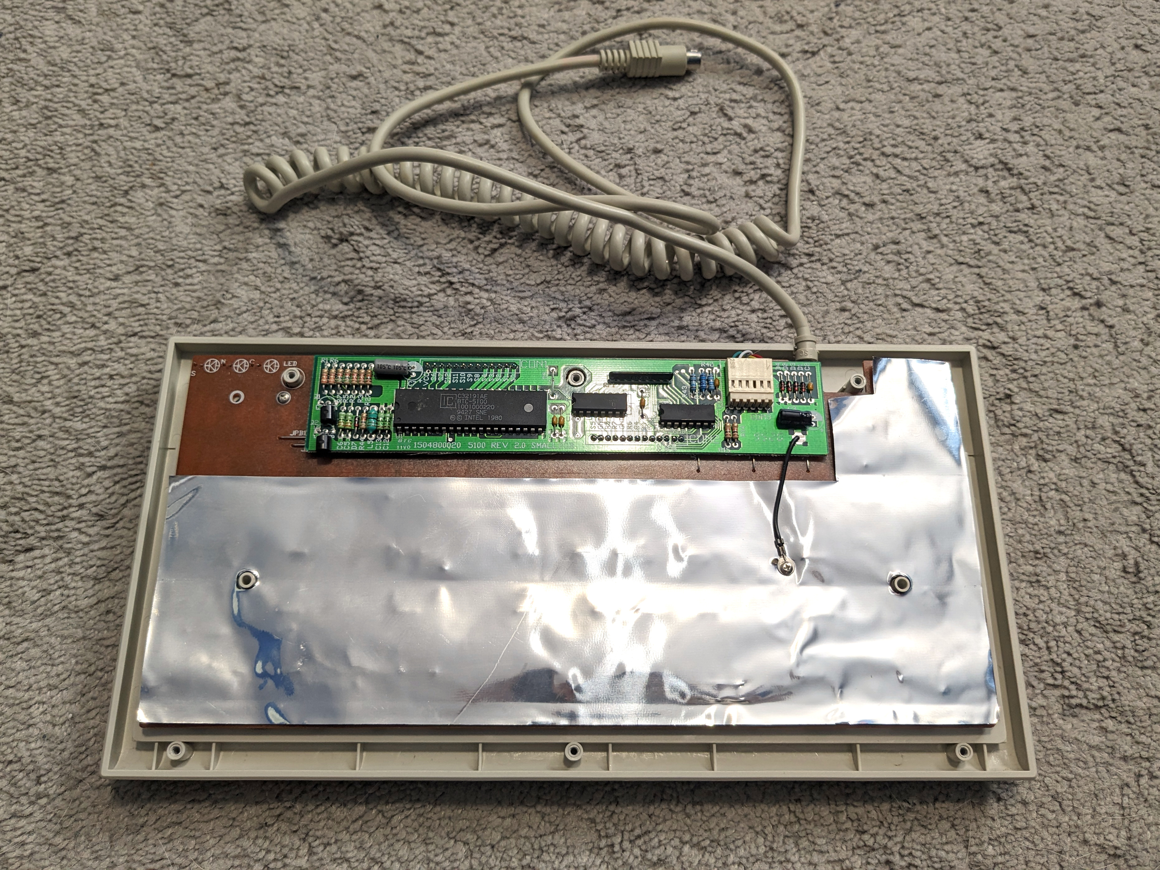
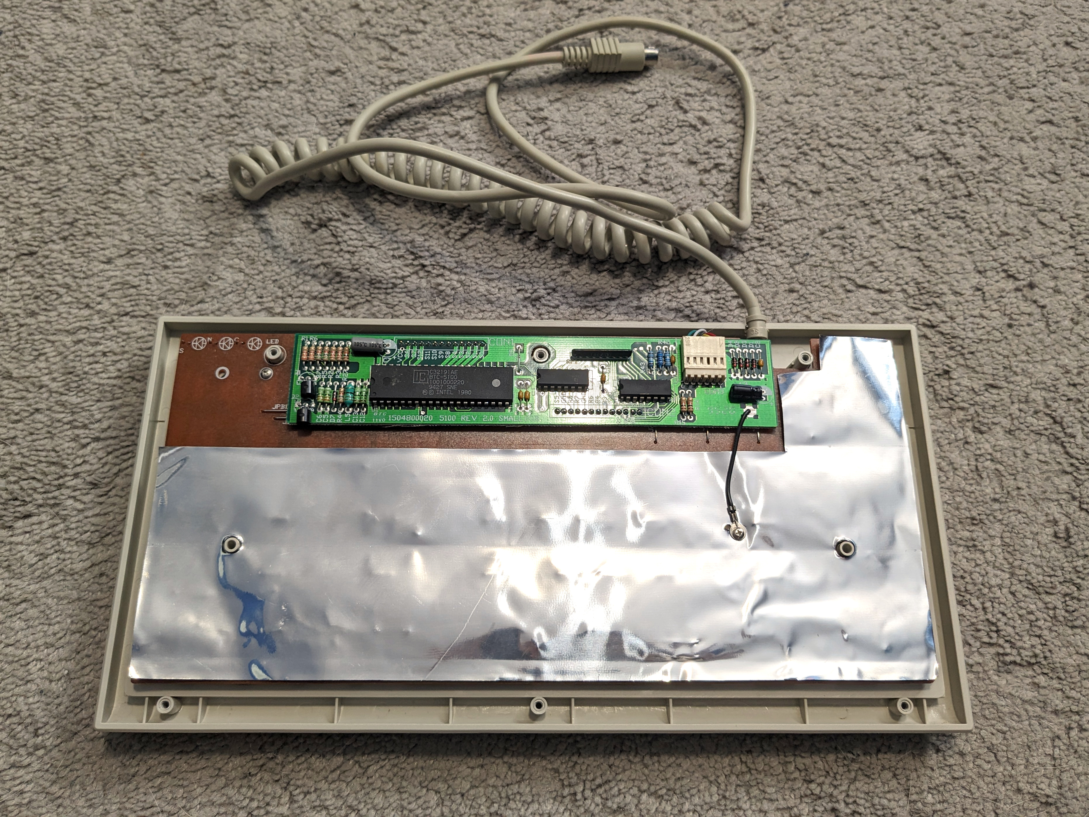
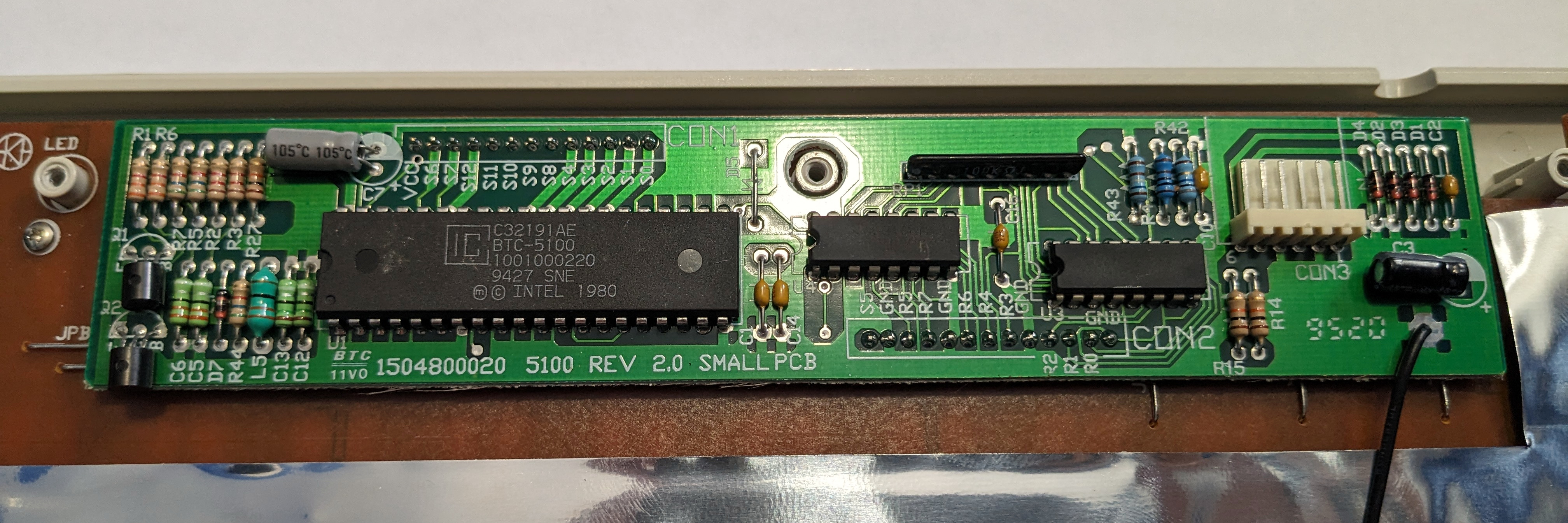
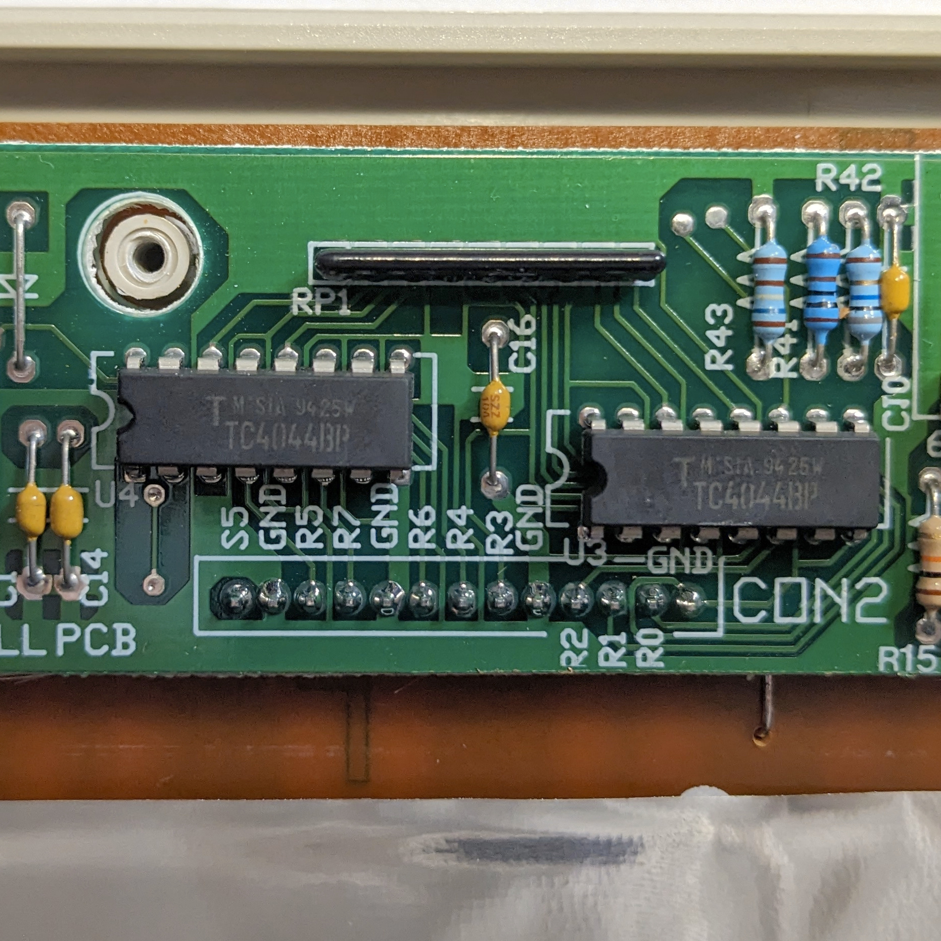
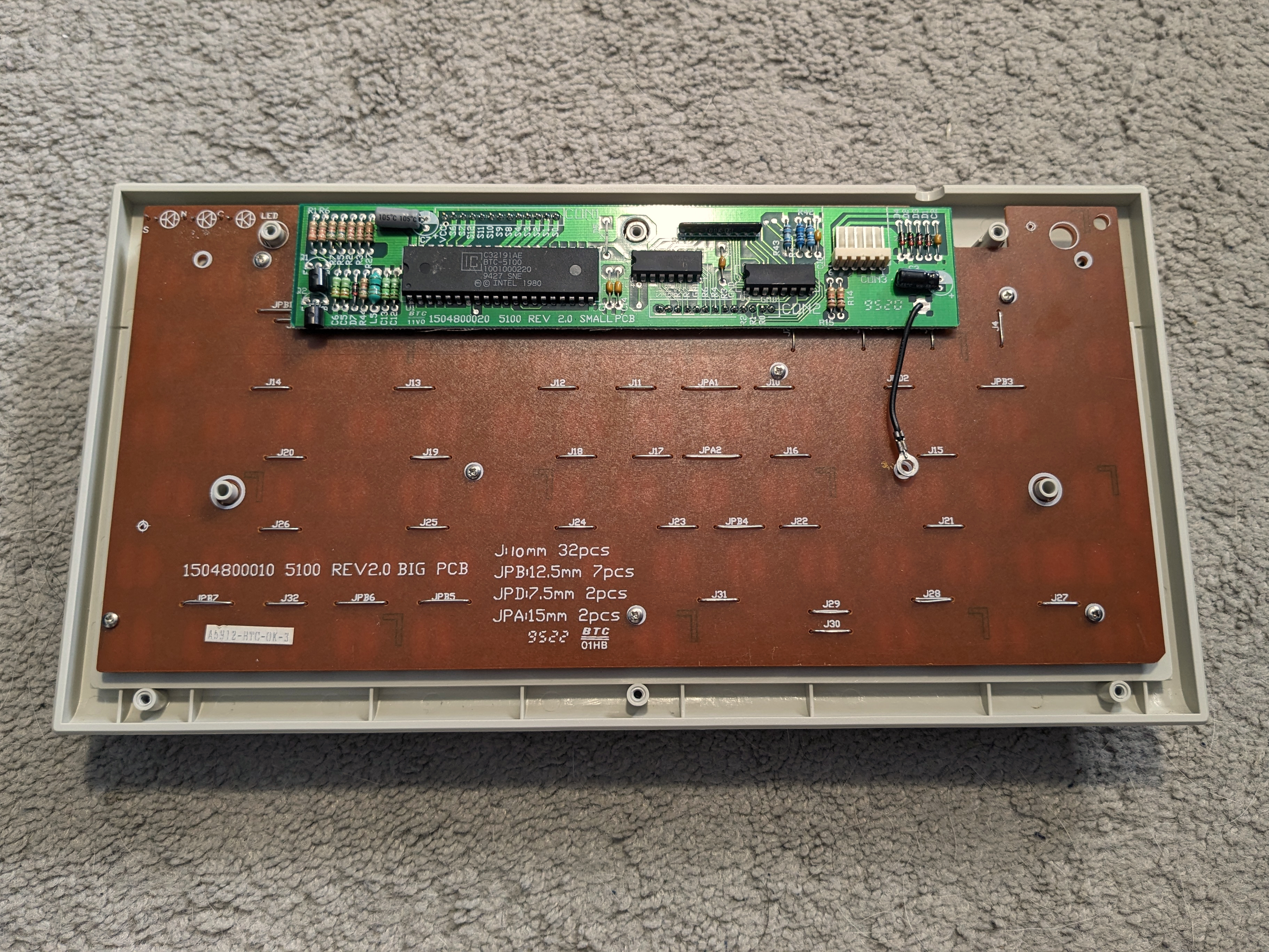
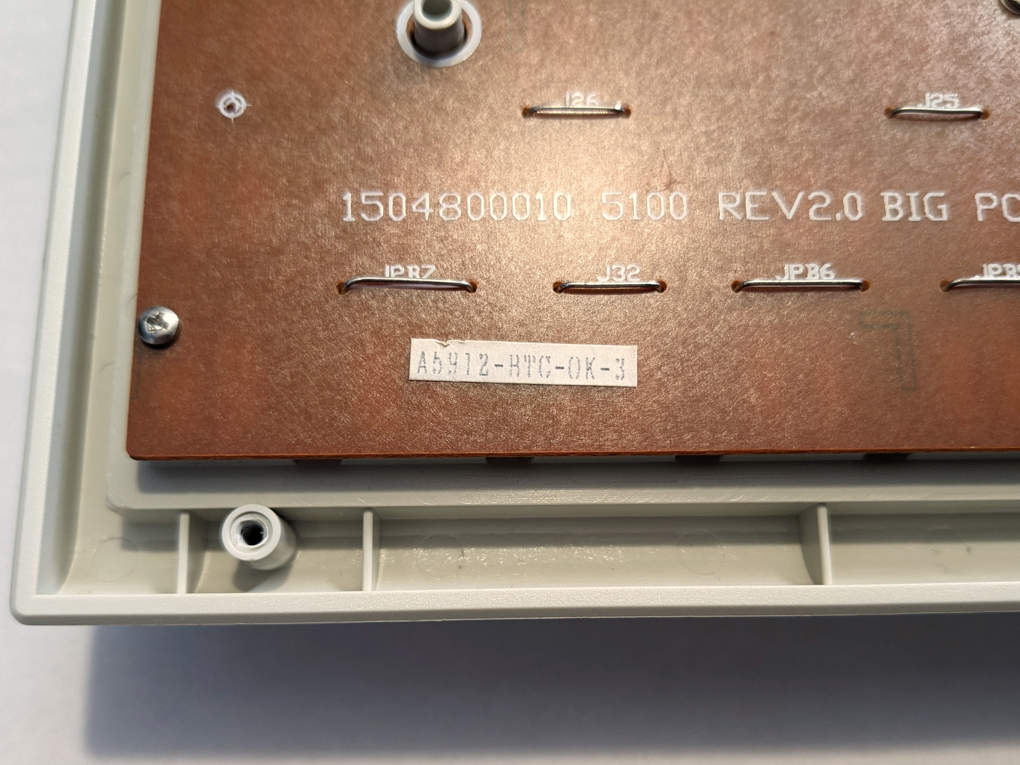
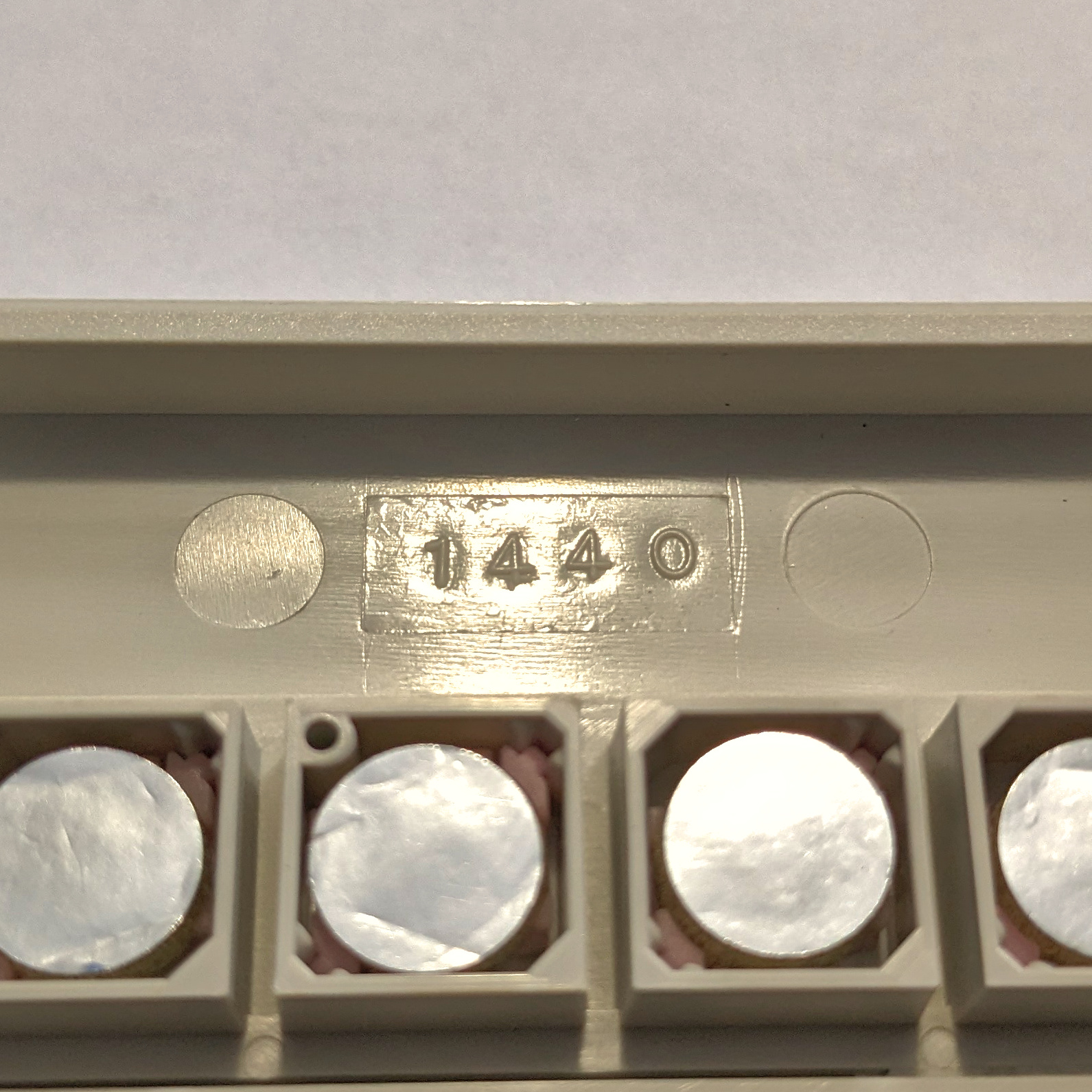
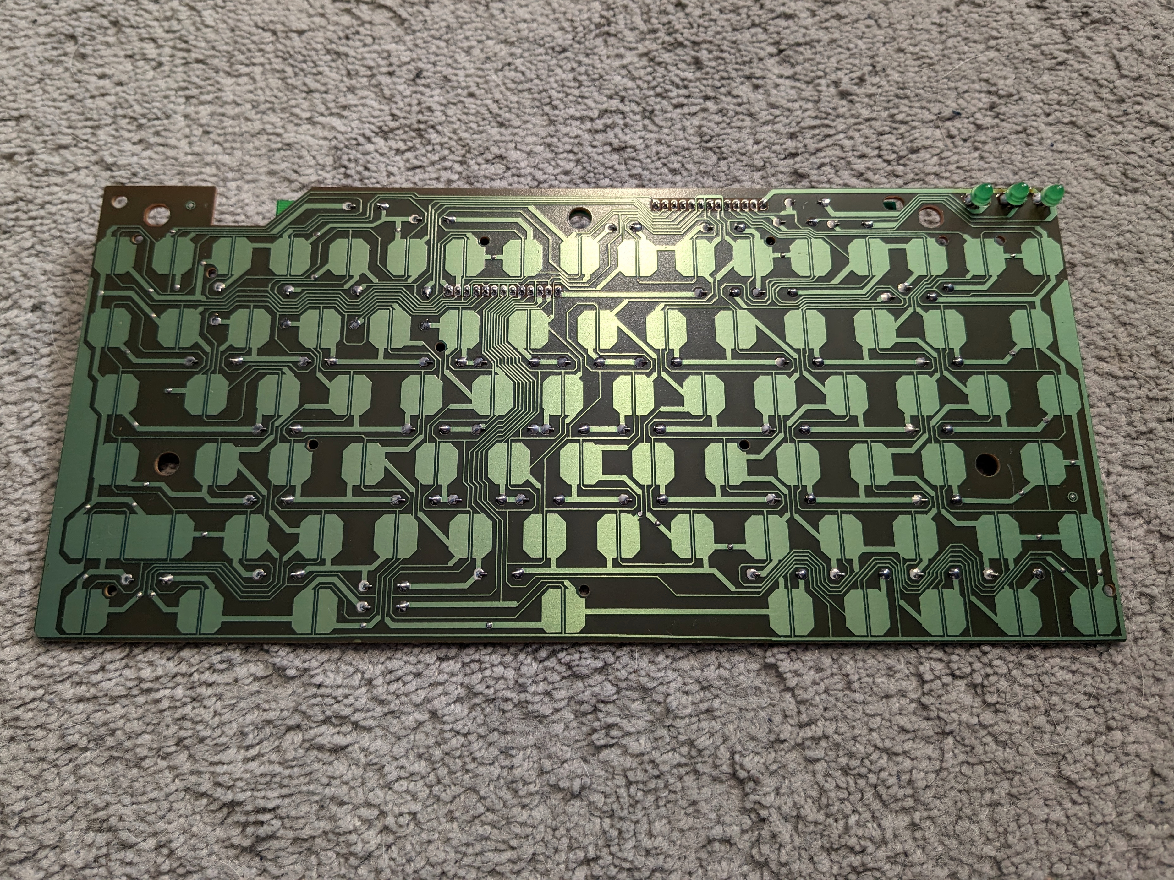
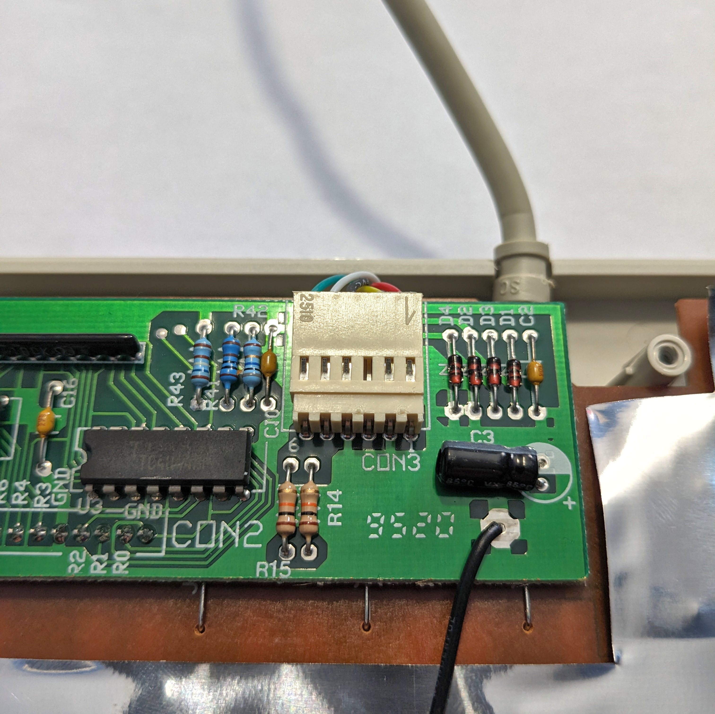
When opening the keyboard, the capacitive PCB can be found screwed into the top case. It consists of the capacitive matrix, LEDs for the lock lights, and jumper wires for the matrix. The PCB is then soldered into a daughterboard that connects with the PCB via pin headers. This daughterboard contains the internal controllers, PCB components, a socket for the cable, and grounding wire which is screwed onto a metal foil that covers most of the backing of the PCB. Both the main PCB and the daughterboard have printing indicating a manufacture date - the first two digits for the year, and the last two is presumed to be for the week.
Including the screw that is used to secure the grounding wire onto the metal foil, the PCB uses 8 screws to secure the PCB into the top case.
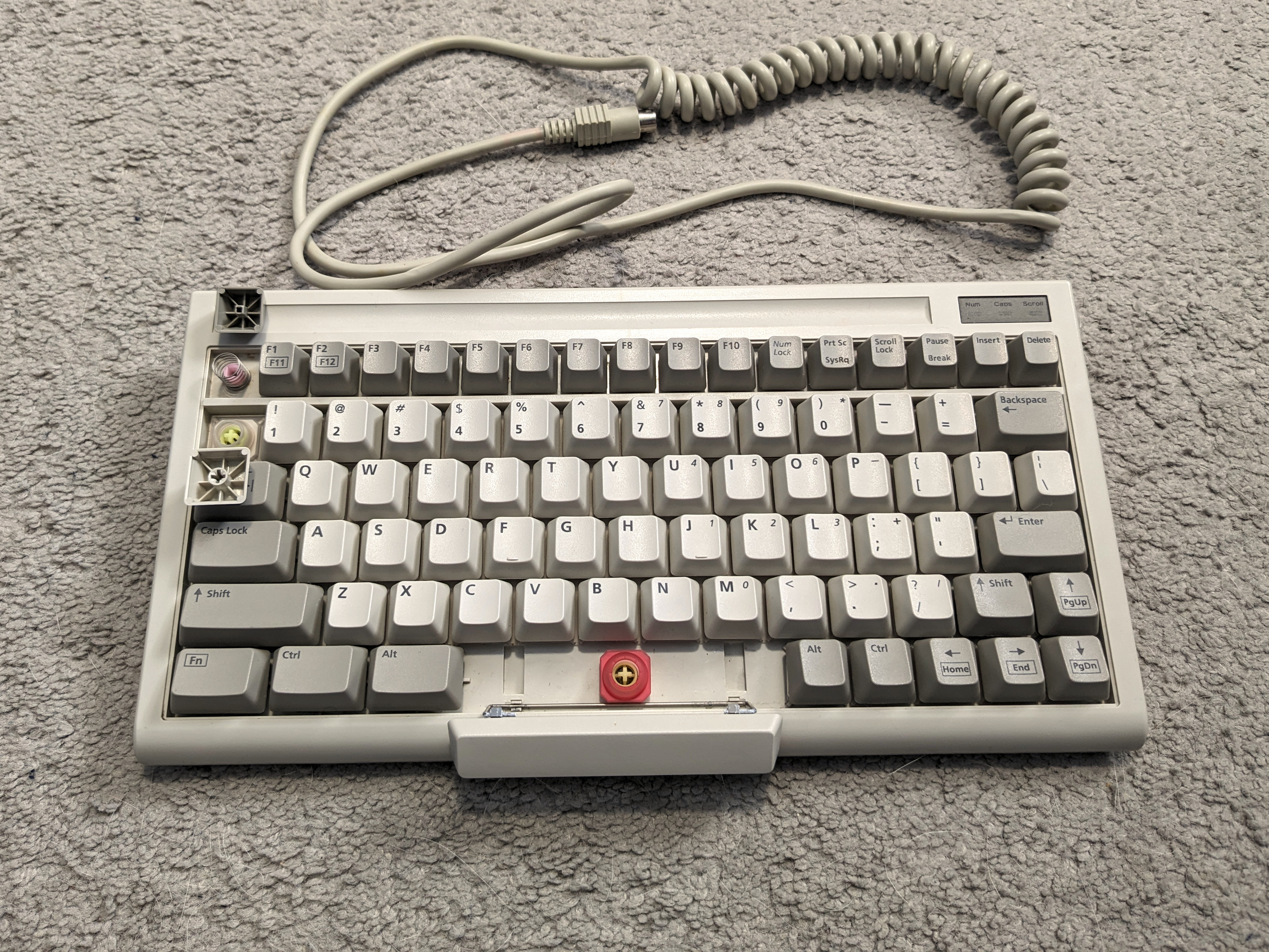
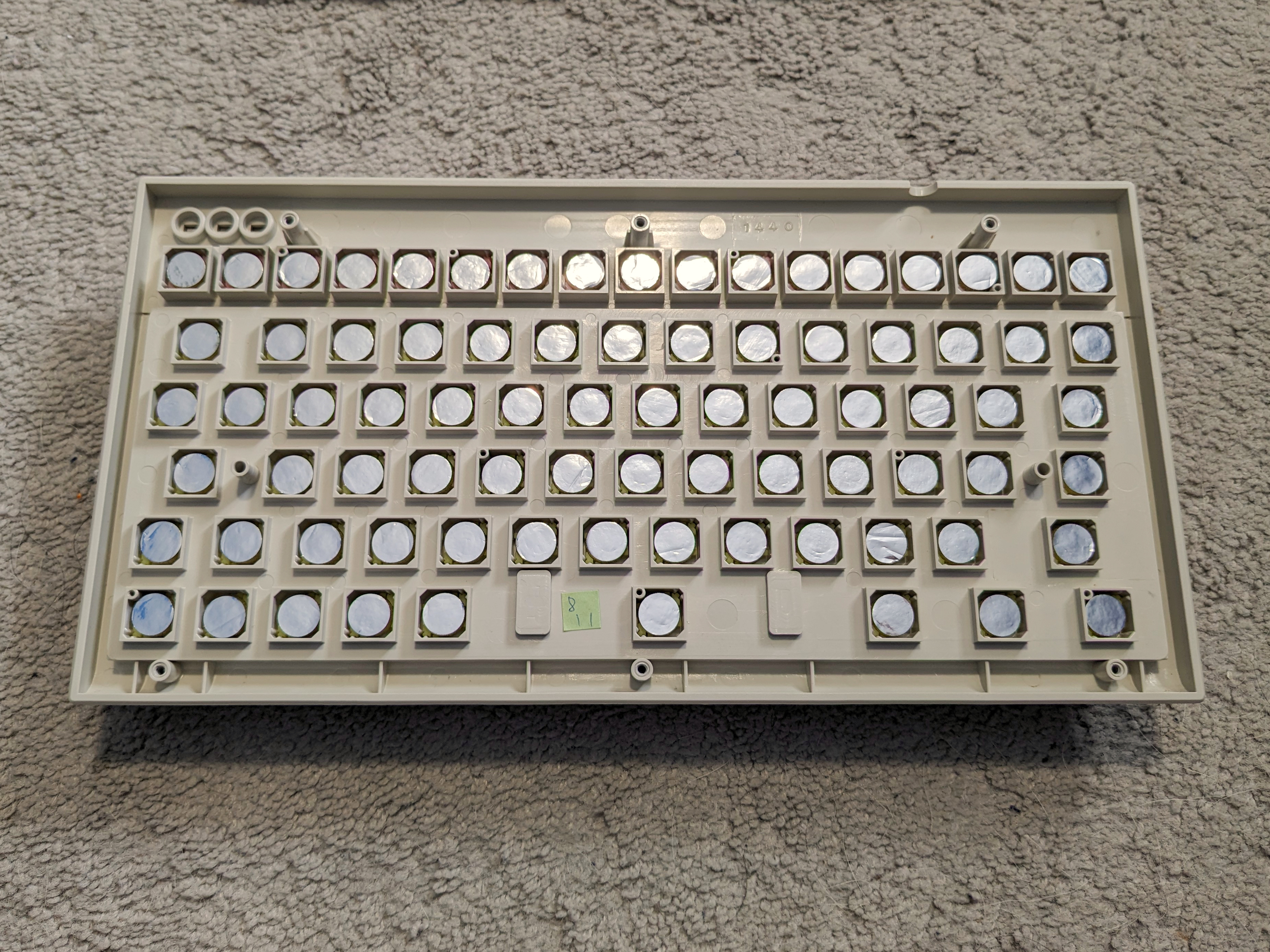
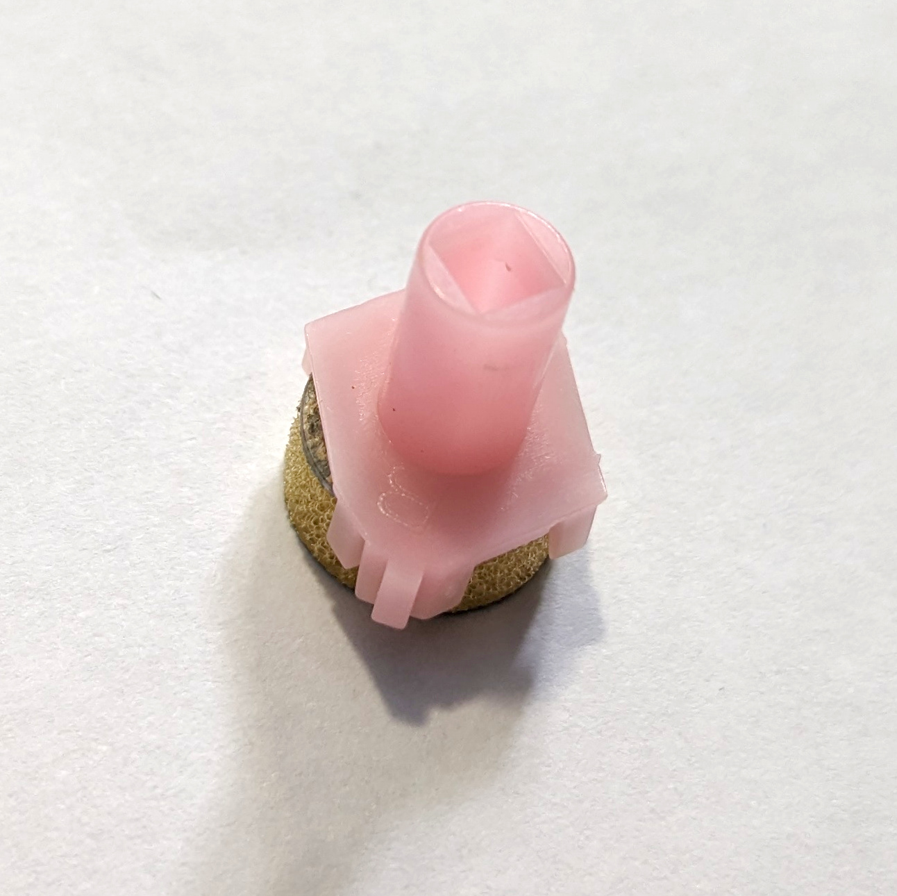
The sliders fit loosely into the top case with its integrated plate and housings, with no clips used to keep the sliders affixed within the housing. The foam and foil pads are affixed onto the slider, with clips in the slider hooking into a plastic backing on the foam pad. The “foil” component is glued into the foam, and consists of a capacitive plastic coated with a foil metal film.
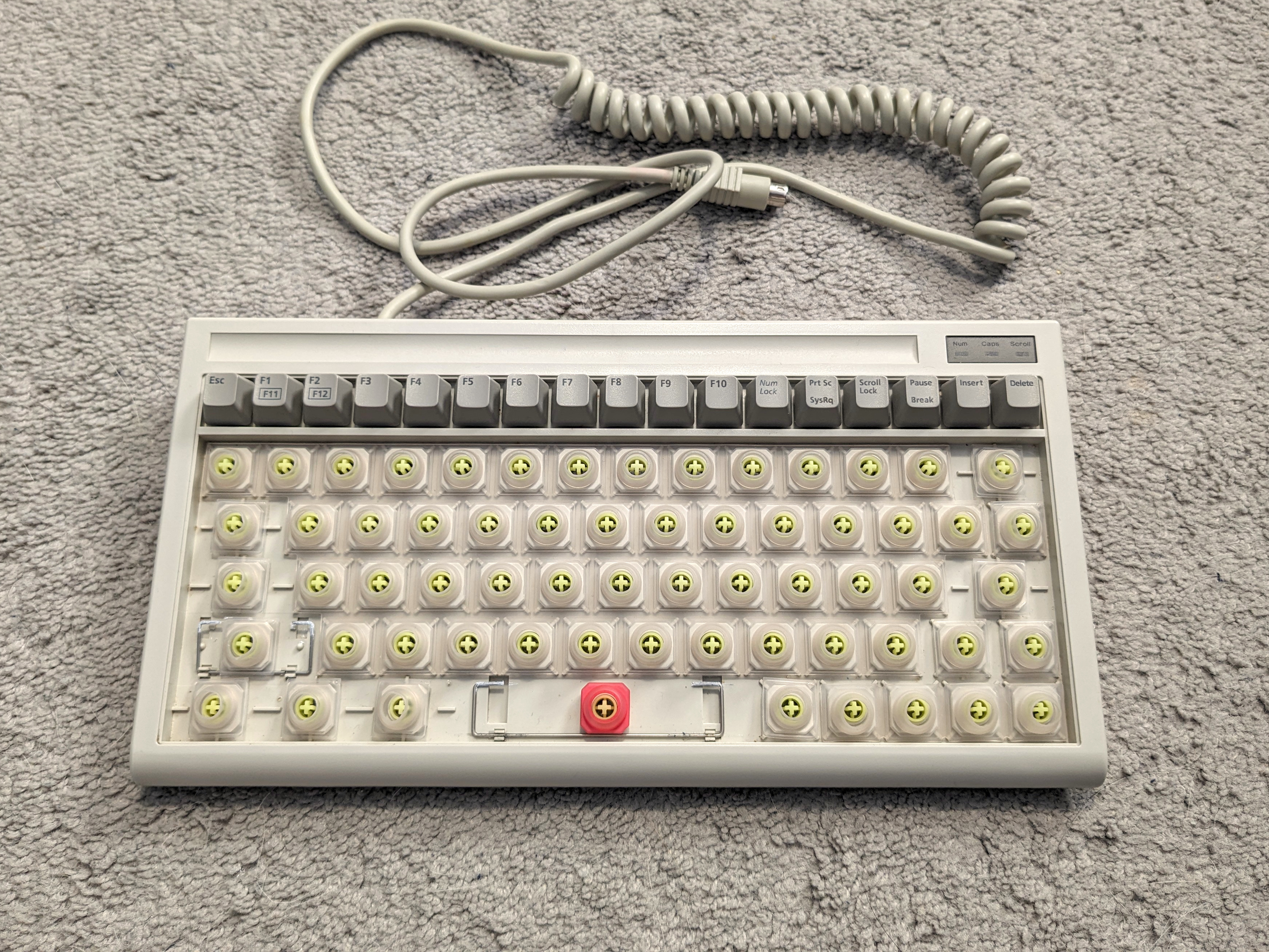
On the external side of the top case, linear springs loosely fit over the sliders for the top row of keys, whilst buckling rubber sleeves are placed over the alphanumeric block. There is a main mat of rubber sleeves that go over the main alphanumeric block excluding the entire right side. Individual buckling rubber sleeves are used for the modifiers, Tab, Caps Lock, “Fn”, Backspace, Enter, and arrow keys. A special red buckling rubber sleeve is used for the spacebar, with the red sleeve being stiffer than the other sleeves.
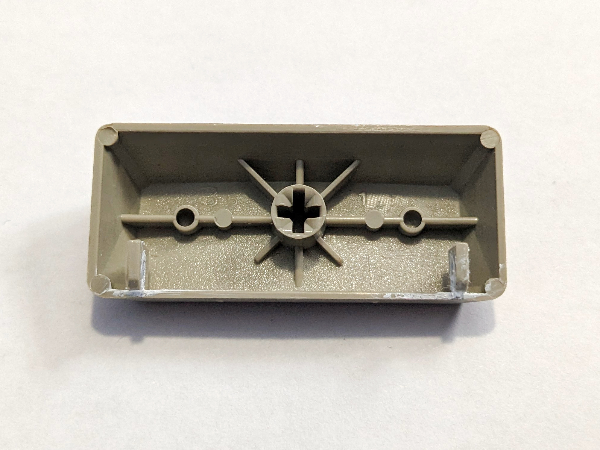
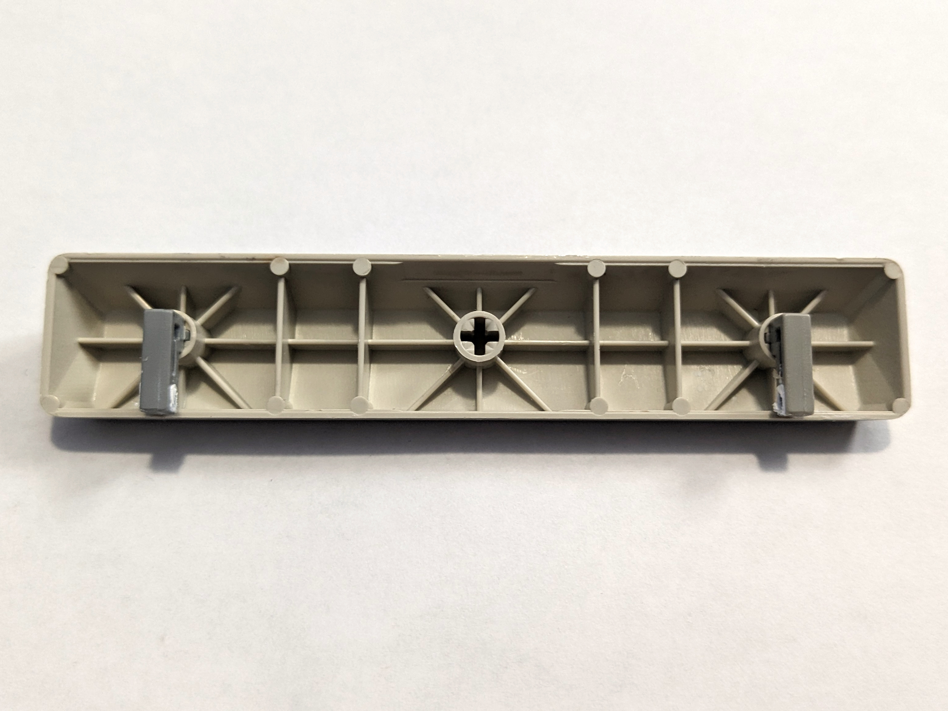
The keyboard has two external wire stabilizers - one for the left shift, and the other for the spacebar. The left shift key has north-facing hooks integrated into the back wall of the keycap, whilst the spacebar has stabilizer inserts tightly inserted into corresponding sockets.
The legending on keycaps can vary depending on when the specific keyboard was made. Older keycaps are presumed to consist of pad printed legends; 2) whilst newer keycaps are laser etched.
The case and keycaps are made out of ABS plastic.
Gallery
BTC 5100 (U.S., PS/2, pearl and pebble 'beige' colourway)
- Daughterboard dated 1995, Week 20.
- PCB dated 1995, Week 22.
- Serial Number: 759185518
- Variant: U.S., 2.0, PS/2.
